Legion ASI Robotics.

AS1 open-source
humanoid robotics.

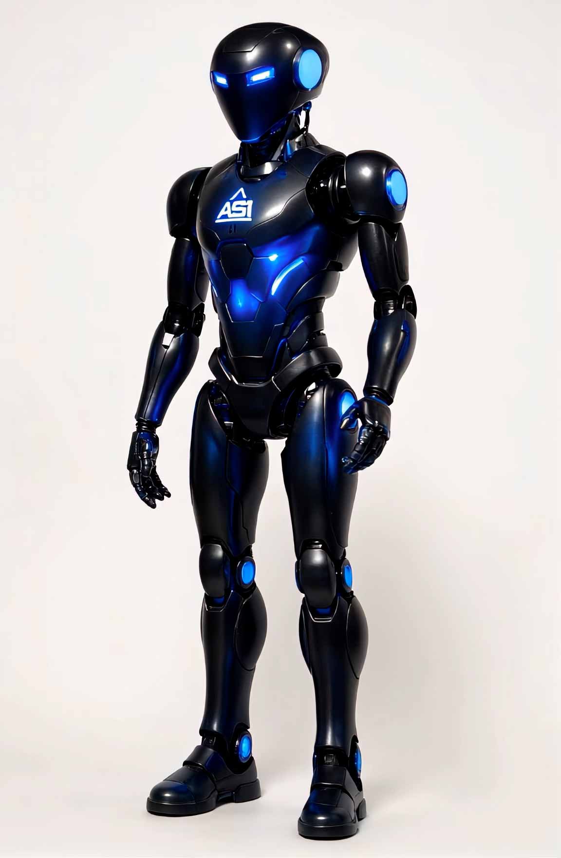
Legion ASI Robotics is developing AS1 as an open-source humanoid robotics platform for embodied AI, distributed control, force sensing, balance, local reasoning, agent memory, bio-displays, and hands-on robotics education. 3D printable parts and build files are coming soon.

Jetson Mini Super Primary Cortex · 24 TOPS target
STM32 Network Distributed Control · regional + limb MCUs
1000Hz Force Loop · weight and balance tracking
Ubuntu + ROS 2 Robotics OS · humanoid control graph
Open-source project
3D printing parts coming soon
Public build documentation planned

AS1 robot

A humanoid robot concept for physical intelligence.

AS1 is not just a robot shell. It is a complete embodied AI research direction: central reasoning, distributed limb control, sensor fusion, force and weight perception, memory systems, visual displays, and a cognitive interface for understanding what the robot is doing.

AS1 demo loop

System overview

AS1 is an open-source humanoid robotics research platform designed for education, research, hands-on innovation, 3D printing, and embodied AI experimentation.

The platform combines consumer-grade 3D printing, off-the-shelf hardware, modular electronics, local AI inference, distributed microcontrollers, and ROS 2 communication. Public 3D printable parts are coming soon.

The robot is designed around a central cognitive layer, regional control boards, limb-level reflex loops, force sensing, balance processing, body displays, and agent-driven diagnostics.

The purpose is to study what happens when memory-driven AI must deal with gravity, friction, force, latency, heat, battery limits, and physical consequences.

Primary compute0TOPS Jetson target
Memory0GB LPDDR5 target
Model0B parameter local robotics LLM
Force loop0Hz weight and balance processing

Interactive viewers

Rotation and walking frame studies.

The original AS1 page used frame-based viewers for rotation and walking simulation. This version keeps that feature, cleans the controls, and preloads nearby frames without locking the page.

Rotation viewer

Scrub through the AS1 rotation frames or play the sequence automatically.

AS1 rotation viewer

Walking simulation

Review AS1 walking frame sequence and gait motion study.

AS1 walking simulation

Robotics is where intelligence has to deal with gravity, weight, friction, heat, power, latency, balance, and consequences.

Legion ASI Robotics statement

Hardware stack

The AS1 body is a distributed nervous system.

The architecture restores the real AS1 story: Jetson compute, STM32 control, CAN bus, force processing, IMUs, encoders, motors, displays, ROS 2 topics, calibration, and cost planning.

01

Primary processor

The NVIDIA Jetson Mini Super is treated as the AS1 cerebral cortex, coordinating high-level cognition, perception, ROS 2 messaging, local model inference, telemetry, planning, and interaction.

  • 12-core ARM CPU cluster target
  • 24 TOPS neural processing target
  • 32GB LPDDR5 system memory
  • 128GB NVMe model and log storage
  • Ubuntu 24.04 LTS with real-time profile
02

Distributed controllers

AS1 uses a body-wide microcontroller network instead of forcing the central processor to handle every physical response. Local MCUs manage limb timing, fast motor loops, safety checks, and fallback behavior.

  • STM32H7 regional control boards
  • STM32G4 limb controller boards
  • CAN bus transceiver network
  • Local actuator response
  • Redundant communication paths
03

Force and weight processing

A dedicated force pathway fuses load cells, force-sensitive resistors, strain gauges, torque sensors, IMUs, and center-of-mass calculations to estimate balance and physical load in real time.

  • 1000Hz processing loop
  • HX711 24-bit ADC modules
  • foot and hand load cells
  • joint torque feedback
  • center-of-mass tracking
04

Sensory network

Vision and proprioception work together. Cameras provide external perception, while IMUs, encoders, strain gauges, and current sensors tell the system what the body is experiencing internally.

  • Robot POV camera
  • wide-angle peripheral camera
  • BNO085 central IMU
  • ICM-20948 distributed 9-axis IMUs
  • AS5048A magnetic encoders
05

Actuation system

Major movement uses BLDC motors with field-oriented control and torque multiplication, while precision and compact movements use digital servos, micro servos, harmonic drives, and planetary gearboxes.

  • 120W BLDC motor class
  • FOC motor drivers
  • planetary gearboxes
  • harmonic drives
  • digital and micro servos
06

Bio-display network

AS1 includes local display hardware to show load, torque, joint state, grip strength, battery, alerts, and diagnostic information directly on the body segment where it matters.

  • OLED limb displays
  • display driver units
  • brightness control
  • UART to limb MCU
  • ROS 2 display topics

AS1 cognitive interface

Dashboard, neural layer, sensors, power, displays, memory, ROS, parts, and testing.

The old page had a large interface with tabs. This rebuild makes the tabs active, renders data through PHP, and adds animated telemetry and dashboard interaction.

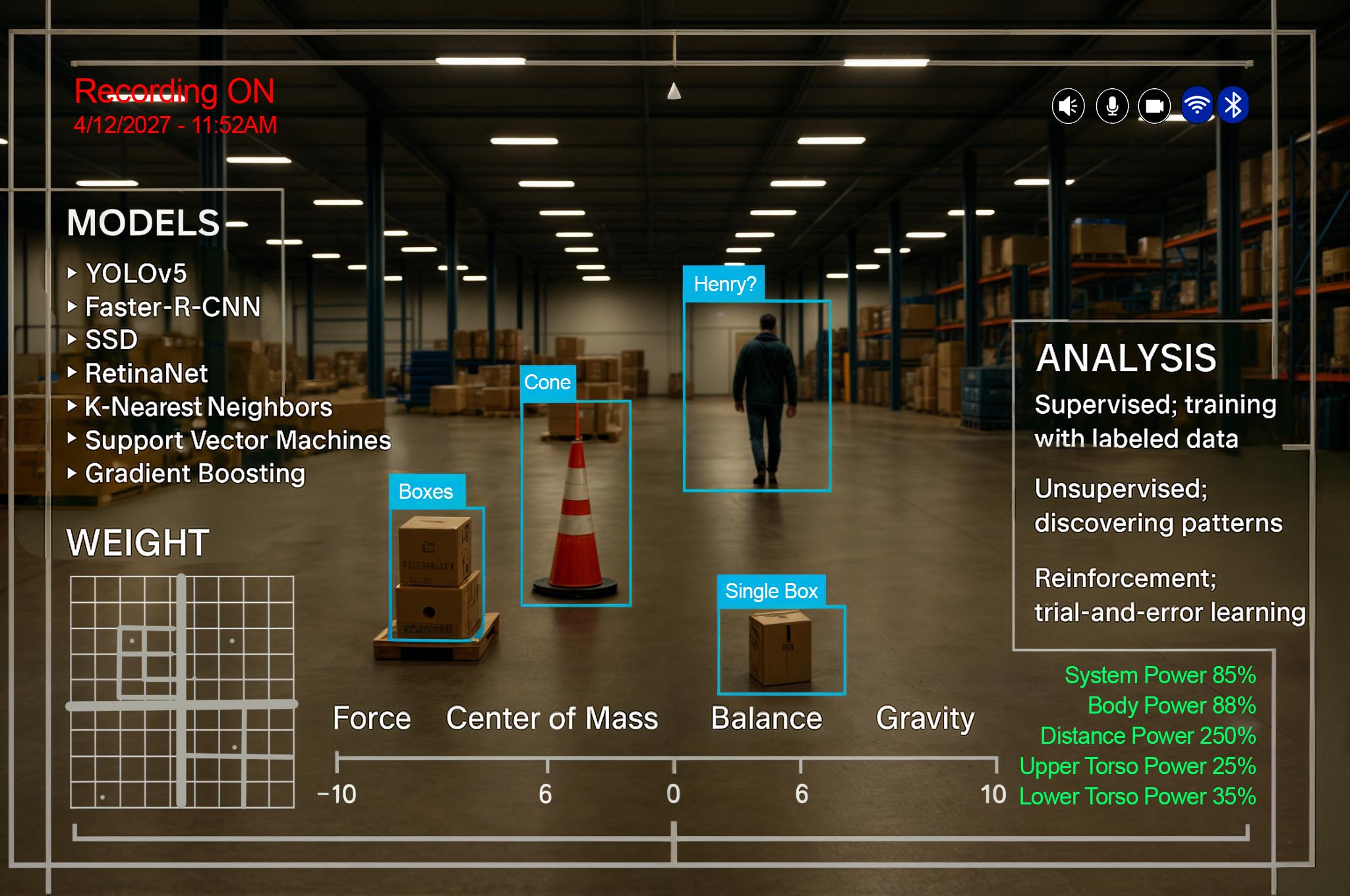
Robot POV
Normal View
AS1 robot point of view HUD
[system] AS1 cognitive layer initialized
[kernel] Ubuntu 24.04 LTS RT profile loaded
[ros2] Humanoid control graph standing by
[balance] Force and center-of-mass model active
[agent] Planning and diagnostics layer ready
Primary processor34%
Memory allocation8.7GB / 32GB
Neural processors58%
Battery87%
Balance statusStable
Force tracking1000Hz
CAN healthNominal
Display networkActive

Local language model

AS1's on-device intelligence layer is based on a quantized 2.5B parameter robotics model intended for untethered operation, task reasoning, and natural language interaction.

2.5B parameters INT8 quantized 15 tokens/sec target 16K context window

Embodied model architecture

The model is optimized for physical control tasks, using proprioceptive embeddings so body position, load, torque, and sensor feedback can become part of reasoning.

Proprioception Physical context Action planning Diagnostics

Hybrid processing

AS1 can operate locally while retaining the option to use cloud resources. If disconnected, the system should degrade gracefully to essential local functions.

Local mode Cloud assist Graceful fallback Telemetry cache

Weight and force reasoning

A specialized reasoning module interprets load, torque, center of mass, and grip data so AS1 can estimate object weight and explain physical interactions.

Load inference Balance prediction Grip analysis Force history

Vision system

The perception stack includes robot POV cameras, peripheral cameras, lens assemblies, and HUD overlays for robot-centered visual understanding.

POV feed Peripheral view HUD overlay Object tracking

Force and weight sensing

Load cells, FSRs, strain gauges, and torque sensors allow AS1 to measure physical interaction, object handling, and balance changes.

Load cells FSRs Strain gauges Torque sensors

Inertial awareness

A central BNO085 IMU and distributed ICM-20948 IMUs provide orientation, acceleration, angular velocity, and gravity vector awareness.

BNO085 ICM-20948 Gravity vector Impact sensing

Joint position tracking

Magnetic encoders provide continuous articulation data so AS1 can understand joint angles, posture, movement state, and kinematic positioning.

AS5048A 37 joint positions Motion feedback Joint state

Control distribution network

Regional STM32H7 boards and limb-level STM32G4 boards form a distributed network where body segments can respond locally while staying coordinated.

STM32H7 STM32G4 CAN bus Regional autonomy

Power distribution

The power layer routes energy to compute, sensors, motors, displays, and controllers while monitoring current and thermal state across the chassis.

Battery pack BMS Buck converters Current sensors

Motor stack

Major joints use BLDC motors with field-oriented control, gear reduction, and driver current sensing.

BLDC motors FOC drivers Gearboxes Harmonic drives

Secondary actuation

Medium and small movements are handled by digital servos and micro servos for minor joints, fingers, panels, and compact mechanisms.

Digital servos Micro servos Finger joints Compact motion

Bio-display network

AS1 uses local displays to show limb status, load data, joint readings, battery state, and system alerts directly on the robot body.

OLED strips Display drivers Brightness control Local status

ROS 2 display topics

Structured topics distribute payloads for limb displays, joint displays, global alerts, weight values, and grip strength.

/as1/display/global /as1/limb_display/armL /as1/joint_display/kneeR weight topics

Display resilience

Each display unit can maintain local information flow and fallback LED signaling if the full display manager fails.

DDU control UART link local fallback CAN override

Data logging and analysis

Display data can be recorded for performance review, load analysis, and troubleshooting after tests are complete.

ROS bags telemetry debug review service history

Working memory

Immediate experience buffer

Stores recent sensory input, operator request, task context, and movement state so AS1 can respond to what just happened.

Long-term memory

Persistent robot experience

Stores useful prior actions, environment notes, calibration results, recurring objects, maps, and failure history.

Procedural memory

Movement and action library

Stores reusable movement sequences, grip strategies, balance responses, and action routines.

Force memory

Weight and balance history

Stores physical experiences around load, torque, center-of-mass, grip force, object lifting, and posture changes.

Agent memory

Task and communication context

Stores operator preferences, diagnostic patterns, task notes, and reasoning summaries from Legion ASI agents.

Diagnostics memory

Maintenance intelligence

Stores sensor drift, servo strain, battery behavior, temperature history, and fault recovery data.

Computational and control $2,235.00

Jetson compute, controller boards, CAN communication, carrier board, and internal network.

Sensors and perception $1,836.00

Cameras, IMUs, encoders, load cells, force sensors, torque sensors, and calibration hardware.

Actuators and mechanical $4,137.00

BLDC motors, gearboxes, harmonic drives, servos, brackets, bearings, and printable structure.

Power and display $2,055.00

Battery, BMS, power distribution, voltage regulation, OLED displays, display drivers, and indicators.

Tools and assembly $350.00

Specialized tools beyond common shop equipment.

Shipping and handling $250.00

Average freight and supplier handling allowance.

Development contingency $500.00

Replacement parts, alternatives, failed parts, and redesign margin.

Optional upgrades $800.00

Expanded displays, stronger actuation, upgraded sensors, or cosmetic refinements.

Total estimated range

The old AS1 cost estimate placed the complete robot with weight sensing, force detection, balance systems, bio-displays, and full capability in the approximate range of $10,363 to $11,763, depending on supplier, selected options, and regional pricing.

TopicLabelDescription
/as1/display/global Global display state Distributes alerts, warnings, system state, and high-priority body-wide information.
/as1/limb_display/armL Left arm display payload Object weight, grip strength, torque, and motion state for left arm display.
/as1/limb_display/armR Right arm display payload Object weight, grip strength, torque, and motion state for right arm display.
/as1/joint_display/kneeR Right knee joint display Joint torque, temperature, active status, and gait-phase status.
/as1/joint_display/kneeL Left knee joint display Joint torque, temperature, active status, and gait-phase status.
/as1/weight/left_foot Left foot load data Calibrated weight, heel-to-toe distribution, and ground contact state.
/as1/weight/right_foot Right foot load data Calibrated weight, heel-to-toe distribution, and ground contact state.
/as1/grip/left_hand Left hand grip data Grip force, estimated object mass, contact surface, and release confidence.
/as1/grip/right_hand Right hand grip data Grip force, estimated object mass, contact surface, and release confidence.
/as1/balance/com Center of mass Current center-of-mass vector and stability margin estimate.
/as1/imu/torso Torso IMU Torso orientation, acceleration, gravity vector, and angular velocity.
/as1/imu/head Head IMU Head orientation, stabilization state, and gaze-frame movement.
/as1/vision/pov Point-of-view camera Primary robot visual stream and HUD overlay source.
/as1/cognitive/log Cognitive log Reasoning, diagnostics, agent notes, and operator-readable summaries.
/as1/motor/command Motor command bus High-level actuator commands routed toward regional controllers.
/as1/safety/state Safety state Emergency stop, degraded mode, motion lock, and watchdog output.
/as1/joint/left_shoulder/state Left shoulder joint state Position, velocity, torque estimate, temperature, current, and health state.
/as1/joint/left_shoulder/command Left shoulder joint command Target position, torque limit, speed limit, motion profile, and safety boundary.
/as1/display/left_shoulder Left shoulder local display Local display payload for health, warning, load, torque, or calibration state.
/as1/joint/left_elbow/state Left elbow joint state Position, velocity, torque estimate, temperature, current, and health state.
/as1/joint/left_elbow/command Left elbow joint command Target position, torque limit, speed limit, motion profile, and safety boundary.
/as1/display/left_elbow Left elbow local display Local display payload for health, warning, load, torque, or calibration state.
/as1/joint/left_wrist/state Left wrist joint state Position, velocity, torque estimate, temperature, current, and health state.
/as1/joint/left_wrist/command Left wrist joint command Target position, torque limit, speed limit, motion profile, and safety boundary.
/as1/display/left_wrist Left wrist local display Local display payload for health, warning, load, torque, or calibration state.
/as1/joint/left_hip/state Left hip joint state Position, velocity, torque estimate, temperature, current, and health state.
/as1/joint/left_hip/command Left hip joint command Target position, torque limit, speed limit, motion profile, and safety boundary.
/as1/display/left_hip Left hip local display Local display payload for health, warning, load, torque, or calibration state.
/as1/joint/left_knee/state Left knee joint state Position, velocity, torque estimate, temperature, current, and health state.
/as1/joint/left_knee/command Left knee joint command Target position, torque limit, speed limit, motion profile, and safety boundary.
/as1/display/left_knee Left knee local display Local display payload for health, warning, load, torque, or calibration state.
/as1/joint/left_ankle/state Left ankle joint state Position, velocity, torque estimate, temperature, current, and health state.
/as1/joint/left_ankle/command Left ankle joint command Target position, torque limit, speed limit, motion profile, and safety boundary.
/as1/display/left_ankle Left ankle local display Local display payload for health, warning, load, torque, or calibration state.
/as1/joint/left_hand/state Left hand joint state Position, velocity, torque estimate, temperature, current, and health state.
/as1/joint/left_hand/command Left hand joint command Target position, torque limit, speed limit, motion profile, and safety boundary.
/as1/display/left_hand Left hand local display Local display payload for health, warning, load, torque, or calibration state.
/as1/joint/left_foot/state Left foot joint state Position, velocity, torque estimate, temperature, current, and health state.
/as1/joint/left_foot/command Left foot joint command Target position, torque limit, speed limit, motion profile, and safety boundary.
/as1/display/left_foot Left foot local display Local display payload for health, warning, load, torque, or calibration state.
/as1/joint/right_shoulder/state Right shoulder joint state Position, velocity, torque estimate, temperature, current, and health state.
/as1/joint/right_shoulder/command Right shoulder joint command Target position, torque limit, speed limit, motion profile, and safety boundary.
/as1/display/right_shoulder Right shoulder local display Local display payload for health, warning, load, torque, or calibration state.
/as1/joint/right_elbow/state Right elbow joint state Position, velocity, torque estimate, temperature, current, and health state.
/as1/joint/right_elbow/command Right elbow joint command Target position, torque limit, speed limit, motion profile, and safety boundary.
/as1/display/right_elbow Right elbow local display Local display payload for health, warning, load, torque, or calibration state.
/as1/joint/right_wrist/state Right wrist joint state Position, velocity, torque estimate, temperature, current, and health state.
/as1/joint/right_wrist/command Right wrist joint command Target position, torque limit, speed limit, motion profile, and safety boundary.
/as1/display/right_wrist Right wrist local display Local display payload for health, warning, load, torque, or calibration state.
/as1/joint/right_hip/state Right hip joint state Position, velocity, torque estimate, temperature, current, and health state.
/as1/joint/right_hip/command Right hip joint command Target position, torque limit, speed limit, motion profile, and safety boundary.
/as1/display/right_hip Right hip local display Local display payload for health, warning, load, torque, or calibration state.
/as1/joint/right_knee/state Right knee joint state Position, velocity, torque estimate, temperature, current, and health state.
/as1/joint/right_knee/command Right knee joint command Target position, torque limit, speed limit, motion profile, and safety boundary.
/as1/display/right_knee Right knee local display Local display payload for health, warning, load, torque, or calibration state.
/as1/joint/right_ankle/state Right ankle joint state Position, velocity, torque estimate, temperature, current, and health state.
/as1/joint/right_ankle/command Right ankle joint command Target position, torque limit, speed limit, motion profile, and safety boundary.
/as1/display/right_ankle Right ankle local display Local display payload for health, warning, load, torque, or calibration state.
/as1/joint/right_hand/state Right hand joint state Position, velocity, torque estimate, temperature, current, and health state.
/as1/joint/right_hand/command Right hand joint command Target position, torque limit, speed limit, motion profile, and safety boundary.
/as1/display/right_hand Right hand local display Local display payload for health, warning, load, torque, or calibration state.
/as1/joint/right_foot/state Right foot joint state Position, velocity, torque estimate, temperature, current, and health state.
/as1/joint/right_foot/command Right foot joint command Target position, torque limit, speed limit, motion profile, and safety boundary.
/as1/display/right_foot Right foot local display Local display payload for health, warning, load, torque, or calibration state.
/as1/calibration/checkpoint_01 Calibration checkpoint 01 Structured output from a repeatable calibration or validation step.
/as1/calibration/checkpoint_02 Calibration checkpoint 02 Structured output from a repeatable calibration or validation step.
/as1/calibration/checkpoint_03 Calibration checkpoint 03 Structured output from a repeatable calibration or validation step.
/as1/calibration/checkpoint_04 Calibration checkpoint 04 Structured output from a repeatable calibration or validation step.
/as1/calibration/checkpoint_05 Calibration checkpoint 05 Structured output from a repeatable calibration or validation step.
/as1/calibration/checkpoint_06 Calibration checkpoint 06 Structured output from a repeatable calibration or validation step.
/as1/calibration/checkpoint_07 Calibration checkpoint 07 Structured output from a repeatable calibration or validation step.
/as1/calibration/checkpoint_08 Calibration checkpoint 08 Structured output from a repeatable calibration or validation step.
/as1/calibration/checkpoint_09 Calibration checkpoint 09 Structured output from a repeatable calibration or validation step.
/as1/calibration/checkpoint_10 Calibration checkpoint 10 Structured output from a repeatable calibration or validation step.
/as1/calibration/checkpoint_11 Calibration checkpoint 11 Structured output from a repeatable calibration or validation step.
/as1/calibration/checkpoint_12 Calibration checkpoint 12 Structured output from a repeatable calibration or validation step.
/as1/calibration/checkpoint_13 Calibration checkpoint 13 Structured output from a repeatable calibration or validation step.
/as1/calibration/checkpoint_14 Calibration checkpoint 14 Structured output from a repeatable calibration or validation step.
/as1/calibration/checkpoint_15 Calibration checkpoint 15 Structured output from a repeatable calibration or validation step.
/as1/calibration/checkpoint_16 Calibration checkpoint 16 Structured output from a repeatable calibration or validation step.
/as1/calibration/checkpoint_17 Calibration checkpoint 17 Structured output from a repeatable calibration or validation step.
/as1/calibration/checkpoint_18 Calibration checkpoint 18 Structured output from a repeatable calibration or validation step.
/as1/calibration/checkpoint_19 Calibration checkpoint 19 Structured output from a repeatable calibration or validation step.
/as1/calibration/checkpoint_20 Calibration checkpoint 20 Structured output from a repeatable calibration or validation step.
/as1/calibration/checkpoint_21 Calibration checkpoint 21 Structured output from a repeatable calibration or validation step.
/as1/calibration/checkpoint_22 Calibration checkpoint 22 Structured output from a repeatable calibration or validation step.
/as1/calibration/checkpoint_23 Calibration checkpoint 23 Structured output from a repeatable calibration or validation step.
/as1/calibration/checkpoint_24 Calibration checkpoint 24 Structured output from a repeatable calibration or validation step.
/as1/calibration/checkpoint_25 Calibration checkpoint 25 Structured output from a repeatable calibration or validation step.
/as1/calibration/checkpoint_26 Calibration checkpoint 26 Structured output from a repeatable calibration or validation step.
/as1/calibration/checkpoint_27 Calibration checkpoint 27 Structured output from a repeatable calibration or validation step.
/as1/calibration/checkpoint_28 Calibration checkpoint 28 Structured output from a repeatable calibration or validation step.
/as1/calibration/checkpoint_29 Calibration checkpoint 29 Structured output from a repeatable calibration or validation step.
/as1/calibration/checkpoint_30 Calibration checkpoint 30 Structured output from a repeatable calibration or validation step.
/as1/calibration/checkpoint_31 Calibration checkpoint 31 Structured output from a repeatable calibration or validation step.
/as1/calibration/checkpoint_32 Calibration checkpoint 32 Structured output from a repeatable calibration or validation step.
/as1/calibration/checkpoint_33 Calibration checkpoint 33 Structured output from a repeatable calibration or validation step.
/as1/calibration/checkpoint_34 Calibration checkpoint 34 Structured output from a repeatable calibration or validation step.
/as1/calibration/checkpoint_35 Calibration checkpoint 35 Structured output from a repeatable calibration or validation step.
/as1/calibration/checkpoint_36 Calibration checkpoint 36 Structured output from a repeatable calibration or validation step.
/as1/calibration/checkpoint_37 Calibration checkpoint 37 Structured output from a repeatable calibration or validation step.
/as1/calibration/checkpoint_38 Calibration checkpoint 38 Structured output from a repeatable calibration or validation step.
/as1/calibration/checkpoint_39 Calibration checkpoint 39 Structured output from a repeatable calibration or validation step.
/as1/calibration/checkpoint_40 Calibration checkpoint 40 Structured output from a repeatable calibration or validation step.
TestPhaseObjectiveEquipmentSuccess condition
T-001 Power bring-up Bench Verify regulated 3.3V, 5V, 12V, and motor rails before connecting actuators. Bench supply, multimeter, thermal camera No uncontrolled current draw; rails within tolerance.
T-002 CAN network test Subsystem Confirm each controller appears on the bus and responds to heartbeat messages. CAN analyzer, firmware console All expected node IDs respond with stable heartbeat.
T-003 Load cell calibration Integration Map raw ADC values to known reference weights. Known weights, HX711 board Calibrated curve remains stable across repeated measurements.
T-004 IMU alignment Full-body Validate orientation reference and limb IMU axes. Motion fixture, known angle block Axis mapping and gravity vector agree with physical orientation.
T-005 Encoder zeroing Prototype Set reference positions for every measured joint. Magnetic encoder console Joint zero position matches mechanical datum.
T-006 Motor driver test Bench Verify FOC motor driver response under low torque limit. Motor fixture, current limit supply Motor moves smoothly and current remains bounded.
T-007 Servo sweep test Subsystem Run controlled servo motion across safe range. Servo tester, controller board No binding, over-current, or endpoint overshoot.
T-008 Display topic test Integration Publish sample payloads to display topics. ROS 2 CLI, display node Correct display receives correct data with low latency.
T-009 Agent diagnostic test Full-body Generate operator-readable explanation of a simulated fault. Legion ASI diagnostic agent Agent explains issue, likely cause, and next action.
T-010 Emergency stop test Prototype Verify motor power interruption and software state transition. E-stop circuit, telemetry log Motion stops and dashboard reports safe locked state.
T-011 Power bring-up Bench Verify regulated 3.3V, 5V, 12V, and motor rails before connecting actuators. Bench supply, multimeter, thermal camera No uncontrolled current draw; rails within tolerance.
T-012 CAN network test Subsystem Confirm each controller appears on the bus and responds to heartbeat messages. CAN analyzer, firmware console All expected node IDs respond with stable heartbeat.
T-013 Load cell calibration Integration Map raw ADC values to known reference weights. Known weights, HX711 board Calibrated curve remains stable across repeated measurements.
T-014 IMU alignment Full-body Validate orientation reference and limb IMU axes. Motion fixture, known angle block Axis mapping and gravity vector agree with physical orientation.
T-015 Encoder zeroing Prototype Set reference positions for every measured joint. Magnetic encoder console Joint zero position matches mechanical datum.
T-016 Motor driver test Bench Verify FOC motor driver response under low torque limit. Motor fixture, current limit supply Motor moves smoothly and current remains bounded.
T-017 Servo sweep test Subsystem Run controlled servo motion across safe range. Servo tester, controller board No binding, over-current, or endpoint overshoot.
T-018 Display topic test Integration Publish sample payloads to display topics. ROS 2 CLI, display node Correct display receives correct data with low latency.
T-019 Agent diagnostic test Full-body Generate operator-readable explanation of a simulated fault. Legion ASI diagnostic agent Agent explains issue, likely cause, and next action.
T-020 Emergency stop test Prototype Verify motor power interruption and software state transition. E-stop circuit, telemetry log Motion stops and dashboard reports safe locked state.
T-021 Power bring-up Bench Verify regulated 3.3V, 5V, 12V, and motor rails before connecting actuators. Bench supply, multimeter, thermal camera No uncontrolled current draw; rails within tolerance.
T-022 CAN network test Subsystem Confirm each controller appears on the bus and responds to heartbeat messages. CAN analyzer, firmware console All expected node IDs respond with stable heartbeat.
T-023 Load cell calibration Integration Map raw ADC values to known reference weights. Known weights, HX711 board Calibrated curve remains stable across repeated measurements.
T-024 IMU alignment Full-body Validate orientation reference and limb IMU axes. Motion fixture, known angle block Axis mapping and gravity vector agree with physical orientation.
T-025 Encoder zeroing Prototype Set reference positions for every measured joint. Magnetic encoder console Joint zero position matches mechanical datum.
T-026 Motor driver test Bench Verify FOC motor driver response under low torque limit. Motor fixture, current limit supply Motor moves smoothly and current remains bounded.
T-027 Servo sweep test Subsystem Run controlled servo motion across safe range. Servo tester, controller board No binding, over-current, or endpoint overshoot.
T-028 Display topic test Integration Publish sample payloads to display topics. ROS 2 CLI, display node Correct display receives correct data with low latency.
T-029 Agent diagnostic test Full-body Generate operator-readable explanation of a simulated fault. Legion ASI diagnostic agent Agent explains issue, likely cause, and next action.
T-030 Emergency stop test Prototype Verify motor power interruption and software state transition. E-stop circuit, telemetry log Motion stops and dashboard reports safe locked state.
T-031 Power bring-up Bench Verify regulated 3.3V, 5V, 12V, and motor rails before connecting actuators. Bench supply, multimeter, thermal camera No uncontrolled current draw; rails within tolerance.
T-032 CAN network test Subsystem Confirm each controller appears on the bus and responds to heartbeat messages. CAN analyzer, firmware console All expected node IDs respond with stable heartbeat.
T-033 Load cell calibration Integration Map raw ADC values to known reference weights. Known weights, HX711 board Calibrated curve remains stable across repeated measurements.
T-034 IMU alignment Full-body Validate orientation reference and limb IMU axes. Motion fixture, known angle block Axis mapping and gravity vector agree with physical orientation.
T-035 Encoder zeroing Prototype Set reference positions for every measured joint. Magnetic encoder console Joint zero position matches mechanical datum.
T-036 Motor driver test Bench Verify FOC motor driver response under low torque limit. Motor fixture, current limit supply Motor moves smoothly and current remains bounded.
T-037 Servo sweep test Subsystem Run controlled servo motion across safe range. Servo tester, controller board No binding, over-current, or endpoint overshoot.
T-038 Display topic test Integration Publish sample payloads to display topics. ROS 2 CLI, display node Correct display receives correct data with low latency.
T-039 Agent diagnostic test Full-body Generate operator-readable explanation of a simulated fault. Legion ASI diagnostic agent Agent explains issue, likely cause, and next action.
T-040 Emergency stop test Prototype Verify motor power interruption and software state transition. E-stop circuit, telemetry log Motion stops and dashboard reports safe locked state.
T-041 Power bring-up Bench Verify regulated 3.3V, 5V, 12V, and motor rails before connecting actuators. Bench supply, multimeter, thermal camera No uncontrolled current draw; rails within tolerance.
T-042 CAN network test Subsystem Confirm each controller appears on the bus and responds to heartbeat messages. CAN analyzer, firmware console All expected node IDs respond with stable heartbeat.
T-043 Load cell calibration Integration Map raw ADC values to known reference weights. Known weights, HX711 board Calibrated curve remains stable across repeated measurements.
T-044 IMU alignment Full-body Validate orientation reference and limb IMU axes. Motion fixture, known angle block Axis mapping and gravity vector agree with physical orientation.
T-045 Encoder zeroing Prototype Set reference positions for every measured joint. Magnetic encoder console Joint zero position matches mechanical datum.
T-046 Motor driver test Bench Verify FOC motor driver response under low torque limit. Motor fixture, current limit supply Motor moves smoothly and current remains bounded.
T-047 Servo sweep test Subsystem Run controlled servo motion across safe range. Servo tester, controller board No binding, over-current, or endpoint overshoot.
T-048 Display topic test Integration Publish sample payloads to display topics. ROS 2 CLI, display node Correct display receives correct data with low latency.
T-049 Agent diagnostic test Full-body Generate operator-readable explanation of a simulated fault. Legion ASI diagnostic agent Agent explains issue, likely cause, and next action.
T-050 Emergency stop test Prototype Verify motor power interruption and software state transition. E-stop circuit, telemetry log Motion stops and dashboard reports safe locked state.
T-051 Power bring-up Bench Verify regulated 3.3V, 5V, 12V, and motor rails before connecting actuators. Bench supply, multimeter, thermal camera No uncontrolled current draw; rails within tolerance.
T-052 CAN network test Subsystem Confirm each controller appears on the bus and responds to heartbeat messages. CAN analyzer, firmware console All expected node IDs respond with stable heartbeat.
T-053 Load cell calibration Integration Map raw ADC values to known reference weights. Known weights, HX711 board Calibrated curve remains stable across repeated measurements.
T-054 IMU alignment Full-body Validate orientation reference and limb IMU axes. Motion fixture, known angle block Axis mapping and gravity vector agree with physical orientation.
T-055 Encoder zeroing Prototype Set reference positions for every measured joint. Magnetic encoder console Joint zero position matches mechanical datum.
T-056 Motor driver test Bench Verify FOC motor driver response under low torque limit. Motor fixture, current limit supply Motor moves smoothly and current remains bounded.
T-057 Servo sweep test Subsystem Run controlled servo motion across safe range. Servo tester, controller board No binding, over-current, or endpoint overshoot.
T-058 Display topic test Integration Publish sample payloads to display topics. ROS 2 CLI, display node Correct display receives correct data with low latency.
T-059 Agent diagnostic test Full-body Generate operator-readable explanation of a simulated fault. Legion ASI diagnostic agent Agent explains issue, likely cause, and next action.
T-060 Emergency stop test Prototype Verify motor power interruption and software state transition. E-stop circuit, telemetry log Motion stops and dashboard reports safe locked state.
T-061 Power bring-up Bench Verify regulated 3.3V, 5V, 12V, and motor rails before connecting actuators. Bench supply, multimeter, thermal camera No uncontrolled current draw; rails within tolerance.
T-062 CAN network test Subsystem Confirm each controller appears on the bus and responds to heartbeat messages. CAN analyzer, firmware console All expected node IDs respond with stable heartbeat.
T-063 Load cell calibration Integration Map raw ADC values to known reference weights. Known weights, HX711 board Calibrated curve remains stable across repeated measurements.
T-064 IMU alignment Full-body Validate orientation reference and limb IMU axes. Motion fixture, known angle block Axis mapping and gravity vector agree with physical orientation.
T-065 Encoder zeroing Prototype Set reference positions for every measured joint. Magnetic encoder console Joint zero position matches mechanical datum.
T-066 Motor driver test Bench Verify FOC motor driver response under low torque limit. Motor fixture, current limit supply Motor moves smoothly and current remains bounded.
T-067 Servo sweep test Subsystem Run controlled servo motion across safe range. Servo tester, controller board No binding, over-current, or endpoint overshoot.
T-068 Display topic test Integration Publish sample payloads to display topics. ROS 2 CLI, display node Correct display receives correct data with low latency.
T-069 Agent diagnostic test Full-body Generate operator-readable explanation of a simulated fault. Legion ASI diagnostic agent Agent explains issue, likely cause, and next action.
T-070 Emergency stop test Prototype Verify motor power interruption and software state transition. E-stop circuit, telemetry log Motion stops and dashboard reports safe locked state.
T-071 Power bring-up Bench Verify regulated 3.3V, 5V, 12V, and motor rails before connecting actuators. Bench supply, multimeter, thermal camera No uncontrolled current draw; rails within tolerance.
T-072 CAN network test Subsystem Confirm each controller appears on the bus and responds to heartbeat messages. CAN analyzer, firmware console All expected node IDs respond with stable heartbeat.
T-073 Load cell calibration Integration Map raw ADC values to known reference weights. Known weights, HX711 board Calibrated curve remains stable across repeated measurements.
T-074 IMU alignment Full-body Validate orientation reference and limb IMU axes. Motion fixture, known angle block Axis mapping and gravity vector agree with physical orientation.
T-075 Encoder zeroing Prototype Set reference positions for every measured joint. Magnetic encoder console Joint zero position matches mechanical datum.
T-076 Motor driver test Bench Verify FOC motor driver response under low torque limit. Motor fixture, current limit supply Motor moves smoothly and current remains bounded.
T-077 Servo sweep test Subsystem Run controlled servo motion across safe range. Servo tester, controller board No binding, over-current, or endpoint overshoot.
T-078 Display topic test Integration Publish sample payloads to display topics. ROS 2 CLI, display node Correct display receives correct data with low latency.
T-079 Agent diagnostic test Full-body Generate operator-readable explanation of a simulated fault. Legion ASI diagnostic agent Agent explains issue, likely cause, and next action.
T-080 Emergency stop test Prototype Verify motor power interruption and software state transition. E-stop circuit, telemetry log Motion stops and dashboard reports safe locked state.
T-081 Power bring-up Bench Verify regulated 3.3V, 5V, 12V, and motor rails before connecting actuators. Bench supply, multimeter, thermal camera No uncontrolled current draw; rails within tolerance.
T-082 CAN network test Subsystem Confirm each controller appears on the bus and responds to heartbeat messages. CAN analyzer, firmware console All expected node IDs respond with stable heartbeat.
T-083 Load cell calibration Integration Map raw ADC values to known reference weights. Known weights, HX711 board Calibrated curve remains stable across repeated measurements.
T-084 IMU alignment Full-body Validate orientation reference and limb IMU axes. Motion fixture, known angle block Axis mapping and gravity vector agree with physical orientation.
T-085 Encoder zeroing Prototype Set reference positions for every measured joint. Magnetic encoder console Joint zero position matches mechanical datum.
T-086 Motor driver test Bench Verify FOC motor driver response under low torque limit. Motor fixture, current limit supply Motor moves smoothly and current remains bounded.
T-087 Servo sweep test Subsystem Run controlled servo motion across safe range. Servo tester, controller board No binding, over-current, or endpoint overshoot.
T-088 Display topic test Integration Publish sample payloads to display topics. ROS 2 CLI, display node Correct display receives correct data with low latency.
T-089 Agent diagnostic test Full-body Generate operator-readable explanation of a simulated fault. Legion ASI diagnostic agent Agent explains issue, likely cause, and next action.
T-090 Emergency stop test Prototype Verify motor power interruption and software state transition. E-stop circuit, telemetry log Motion stops and dashboard reports safe locked state.
T-091 Power bring-up Bench Verify regulated 3.3V, 5V, 12V, and motor rails before connecting actuators. Bench supply, multimeter, thermal camera No uncontrolled current draw; rails within tolerance.
T-092 CAN network test Subsystem Confirm each controller appears on the bus and responds to heartbeat messages. CAN analyzer, firmware console All expected node IDs respond with stable heartbeat.
T-093 Load cell calibration Integration Map raw ADC values to known reference weights. Known weights, HX711 board Calibrated curve remains stable across repeated measurements.
T-094 IMU alignment Full-body Validate orientation reference and limb IMU axes. Motion fixture, known angle block Axis mapping and gravity vector agree with physical orientation.
T-095 Encoder zeroing Prototype Set reference positions for every measured joint. Magnetic encoder console Joint zero position matches mechanical datum.
T-096 Motor driver test Bench Verify FOC motor driver response under low torque limit. Motor fixture, current limit supply Motor moves smoothly and current remains bounded.
T-097 Servo sweep test Subsystem Run controlled servo motion across safe range. Servo tester, controller board No binding, over-current, or endpoint overshoot.
T-098 Display topic test Integration Publish sample payloads to display topics. ROS 2 CLI, display node Correct display receives correct data with low latency.
T-099 Agent diagnostic test Full-body Generate operator-readable explanation of a simulated fault. Legion ASI diagnostic agent Agent explains issue, likely cause, and next action.
T-100 Emergency stop test Prototype Verify motor power interruption and software state transition. E-stop circuit, telemetry log Motion stops and dashboard reports safe locked state.
T-101 Power bring-up Bench Verify regulated 3.3V, 5V, 12V, and motor rails before connecting actuators. Bench supply, multimeter, thermal camera No uncontrolled current draw; rails within tolerance.
T-102 CAN network test Subsystem Confirm each controller appears on the bus and responds to heartbeat messages. CAN analyzer, firmware console All expected node IDs respond with stable heartbeat.
T-103 Load cell calibration Integration Map raw ADC values to known reference weights. Known weights, HX711 board Calibrated curve remains stable across repeated measurements.
T-104 IMU alignment Full-body Validate orientation reference and limb IMU axes. Motion fixture, known angle block Axis mapping and gravity vector agree with physical orientation.
T-105 Encoder zeroing Prototype Set reference positions for every measured joint. Magnetic encoder console Joint zero position matches mechanical datum.
T-106 Motor driver test Bench Verify FOC motor driver response under low torque limit. Motor fixture, current limit supply Motor moves smoothly and current remains bounded.
T-107 Servo sweep test Subsystem Run controlled servo motion across safe range. Servo tester, controller board No binding, over-current, or endpoint overshoot.
T-108 Display topic test Integration Publish sample payloads to display topics. ROS 2 CLI, display node Correct display receives correct data with low latency.
T-109 Agent diagnostic test Full-body Generate operator-readable explanation of a simulated fault. Legion ASI diagnostic agent Agent explains issue, likely cause, and next action.
T-110 Emergency stop test Prototype Verify motor power interruption and software state transition. E-stop circuit, telemetry log Motion stops and dashboard reports safe locked state.
T-111 Power bring-up Bench Verify regulated 3.3V, 5V, 12V, and motor rails before connecting actuators. Bench supply, multimeter, thermal camera No uncontrolled current draw; rails within tolerance.
T-112 CAN network test Subsystem Confirm each controller appears on the bus and responds to heartbeat messages. CAN analyzer, firmware console All expected node IDs respond with stable heartbeat.
T-113 Load cell calibration Integration Map raw ADC values to known reference weights. Known weights, HX711 board Calibrated curve remains stable across repeated measurements.
T-114 IMU alignment Full-body Validate orientation reference and limb IMU axes. Motion fixture, known angle block Axis mapping and gravity vector agree with physical orientation.
T-115 Encoder zeroing Prototype Set reference positions for every measured joint. Magnetic encoder console Joint zero position matches mechanical datum.
T-116 Motor driver test Bench Verify FOC motor driver response under low torque limit. Motor fixture, current limit supply Motor moves smoothly and current remains bounded.
T-117 Servo sweep test Subsystem Run controlled servo motion across safe range. Servo tester, controller board No binding, over-current, or endpoint overshoot.
T-118 Display topic test Integration Publish sample payloads to display topics. ROS 2 CLI, display node Correct display receives correct data with low latency.
T-119 Agent diagnostic test Full-body Generate operator-readable explanation of a simulated fault. Legion ASI diagnostic agent Agent explains issue, likely cause, and next action.
T-120 Emergency stop test Prototype Verify motor power interruption and software state transition. E-stop circuit, telemetry log Motion stops and dashboard reports safe locked state.

Open-source downloads

AS1 build files, 3D printing parts, software, and documentation.

AS1 is being organized as an open-source robotics project. The temporary components list is available now as a text download. Printable 3D parts, CAD files, wiring diagrams, firmware, ROS 2 packages, and assembly guides are listed here as public release targets.

AS1 Components List

Temporary text download listing the AS1 hardware stack, sensors, electronics, tools, and early component notes.

TXT Available now

Full Bill of Materials

Structured BOM with quantities, vendors, part numbers, estimated cost, priority, notes, and replacement options.

CSV / XLSX Coming soon
Coming soon

3D Printable Parts Pack

Printable AS1 robot shell, brackets, covers, mounts, display bezels, sensor holders, and prototype body parts.

STL / ZIP Coming soon
Coming soon

CAD Assembly Files

Editable mechanical assemblies for robotics contributors who want to inspect, remix, or improve the AS1 design.

STEP / F3D Coming soon
Coming soon

Slicer Profiles

Recommended prototype print profiles for PETG, PLA+, and nylon carbon fiber parts.

3MF / INI Coming soon
Coming soon

Electronics Wiring Diagrams

Power distribution, CAN bus wiring, STM32 controller layout, display wiring, and sensor routing diagrams.

PDF Coming soon
Coming soon

Jetson Setup Guide

Operating system setup, ROS 2 install notes, camera setup, local model configuration, and service startup guide.

MD / PDF Coming soon
Coming soon

STM32 Firmware Pack

Regional controller and limb controller firmware source for distributed motion, sensing, and display communication.

ZIP Coming soon
Coming soon

ROS 2 Workspace

ROS 2 packages, launch files, message definitions, simulated topics, and diagnostic nodes for AS1 development.

ZIP / GitHub Coming soon
Coming soon

Calibration Worksheets

Load cell, IMU, encoder, torque sensor, grip force, and balance calibration worksheets.

PDF / TXT Coming soon
Coming soon

Assembly Guide

Step-by-step open-source assembly notes for frame, electronics, sensors, displays, controller boards, and test order.

PDF Coming soon
Coming soon

Safety and Bench-Test Checklist

Early testing checklist for power bring-up, actuator limits, emergency stop behavior, sensor validation, and safe operation.

PDF / TXT Coming soon
Coming soon
Open-source release note: AS1 downloadables will be released in stages so builders can validate one layer at a time: components first, then 3D printable parts, then CAD, electronics, firmware, ROS 2 packages, calibration, and assembly documentation.

Components list

Download the AS1 components list as a text file.

For now, the public components list is a simple downloadable text page. The full BOM spreadsheet with vendors, part numbers, replacement options, and priority columns will be released later with the open-source hardware package.

AS1 Components List

Includes the current AS1 compute, control, sensor, actuation, mechanical, display, power, audio, tooling, calibration, harnessing, safety, and telemetry component categories.

Download components text file

Development program

From humanoid prototype to embodied AI platform.

AS1 is presented as a staged open-source robotics platform: mechanical structure, 3D printable parts, distributed electronics, force-aware sensing, cognitive control, bio-displays, and human-safe autonomy.

Mechanical foundation

The AS1 frame is designed around modular 3D printed structural components, serviceable joints, electronics bays, and a humanoid form factor. Public printable parts are planned so builders can inspect, print, test, and improve the design.

Distributed control network

A central Jetson compute unit coordinates regional STM32 controllers distributed through the body, allowing fast local motor response while preserving higher-level cognitive planning.

Force and balance intelligence

The robot interprets load cells, torque sensors, strain gauges, IMUs, and encoders to build an internal model of posture, weight distribution, grip force, and center-of-mass stability.

ROS 2 communication layer

AS1 organizes sensor data, motor commands, diagnostics, display states, and cognitive messages through ROS 2 topics so hardware, software, and agents share one language.

Agent-based cognition

Legion ASI agents provide a higher reasoning layer for diagnostics, planning, task interpretation, memory, and explanation so the robot can describe its own state and assist its own operation.

Open robotics research

AS1 is positioned as a research and education platform for embodied AI, machine perception, physical memory, balance control, and practical human-facing robotic intelligence.

Legion ASI Robotics

AS1 is our path toward embodied artificial intelligence.

The robotics program connects hardware, sensors, movement, memory, agent reasoning, display feedback, and alignment into one physical research platform.